Model III Disassembly & Repair Part 3

Knowing now that the computer itself was functional, I set off to repair the connections between the Main Logic Board, Floppy Controller Card , and RS232 Card.  As shown in a previous post, the flexible flat ribbon cable that connected between the the main logic board and the two daughter boards had deteriorated to the point of no return.  A previous owner had attempted to shove one of the cables into the connector failing miserably.

img_0195

Based on the information that these cables are few and far between and quite hard/expensive to come by, I opted for a repair that would eliminate them altogether.  This option is replacing the 4 flat ribbon connectors with pin headers and using short IDC cables to connect between them.

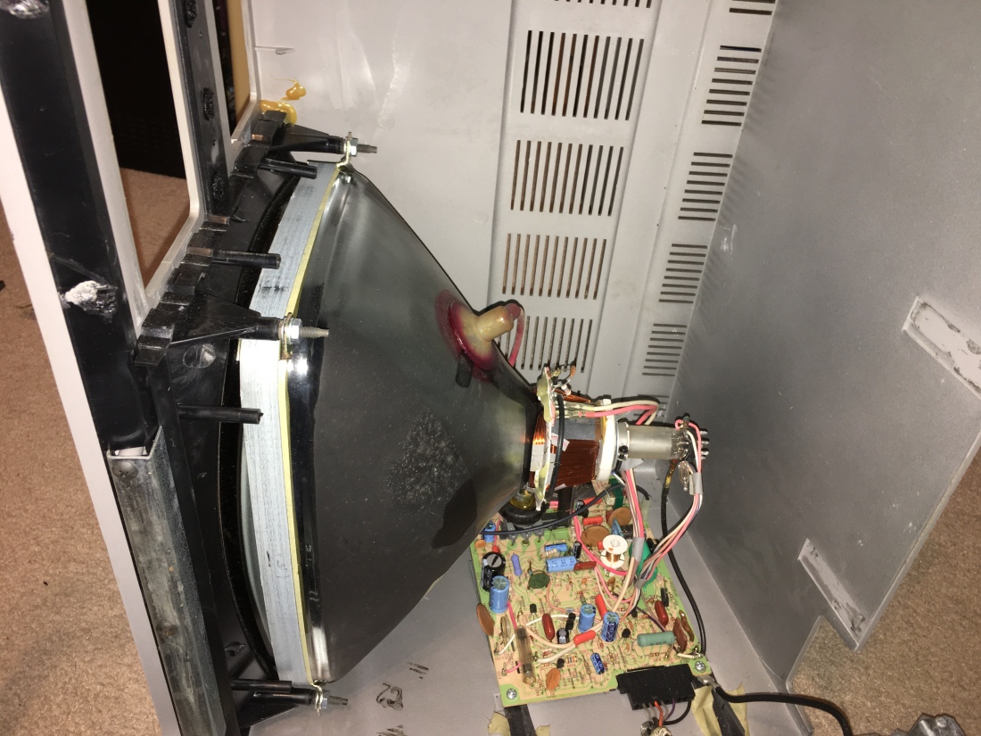
I began by removing the main logic board and two daughter boards from the chassis.  When doing this, be sure to use an anti-static strap to prevent any chance of static damage to the boards.  Once the boards were removed, I proceeded to remove the flat ribbon cable connectors.  The easiest way I found to do this was to snip the plastic at each end of the connector then remove it leaving the pins exposed.  Alternately, you can rock the connector back and forth until the pins fatigue and break, but you have less left to grab during removal.  This is what I was left with once the plastic was removed.

IMG_0222(2)I then proceeded to one by one, grab a pin with tweezers, heat the solder, and remove the pin. MAKE SURE THE SOLDER IS FLUID BEFORE PULLING ON THE PIN OTHERWISE TRACES COULD PULL UP WITH THE SOLDER!  I AM NOT RESPONSIBLE IF YOU DAMAGE YOUR BOARD DURING THIS PROCESS.  PLEASE EXCERSIZE CAUTION.

Once all the pins were removed, I added fresh solder to all the locations, then one by one remove the solder with a solder sucker.  Any remaining solder was removed with solder wick.  The result after removal was a nice clean row of open holes ready for pin header installation.

IMG_0223(1)IMG_0224(2)IMG_0225(2)IMG_0220(2)
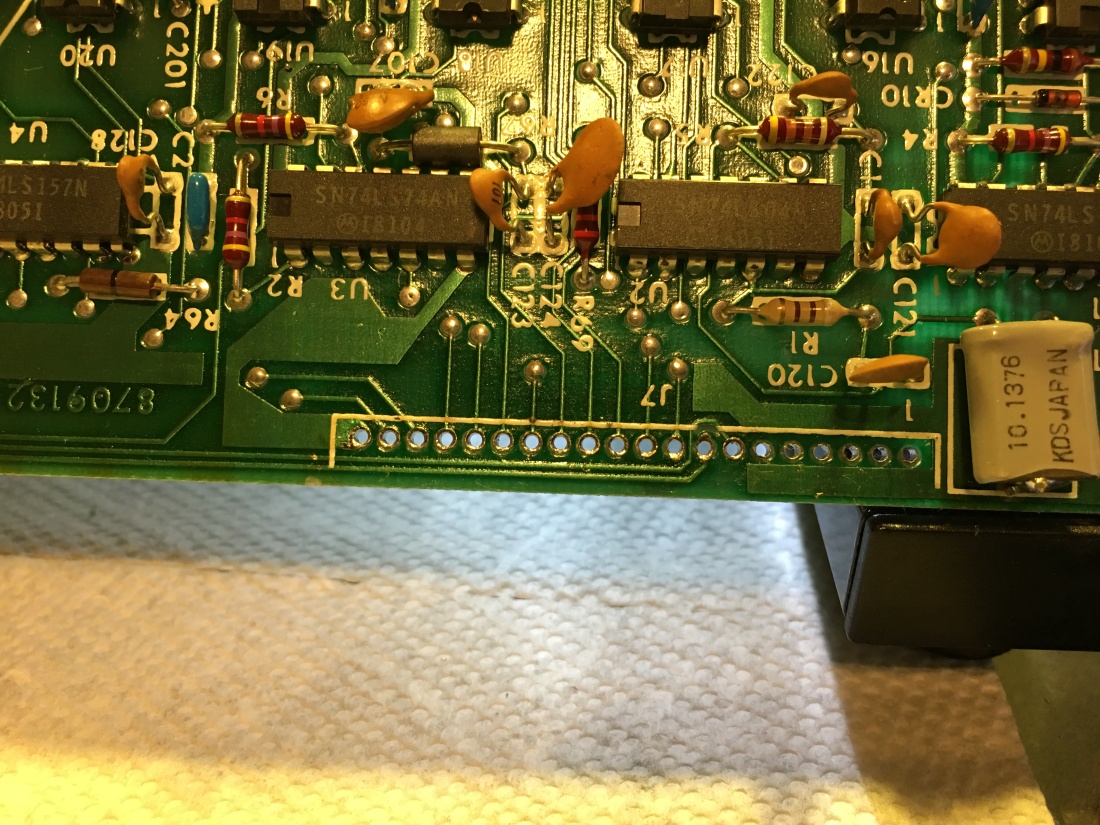
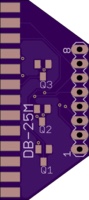
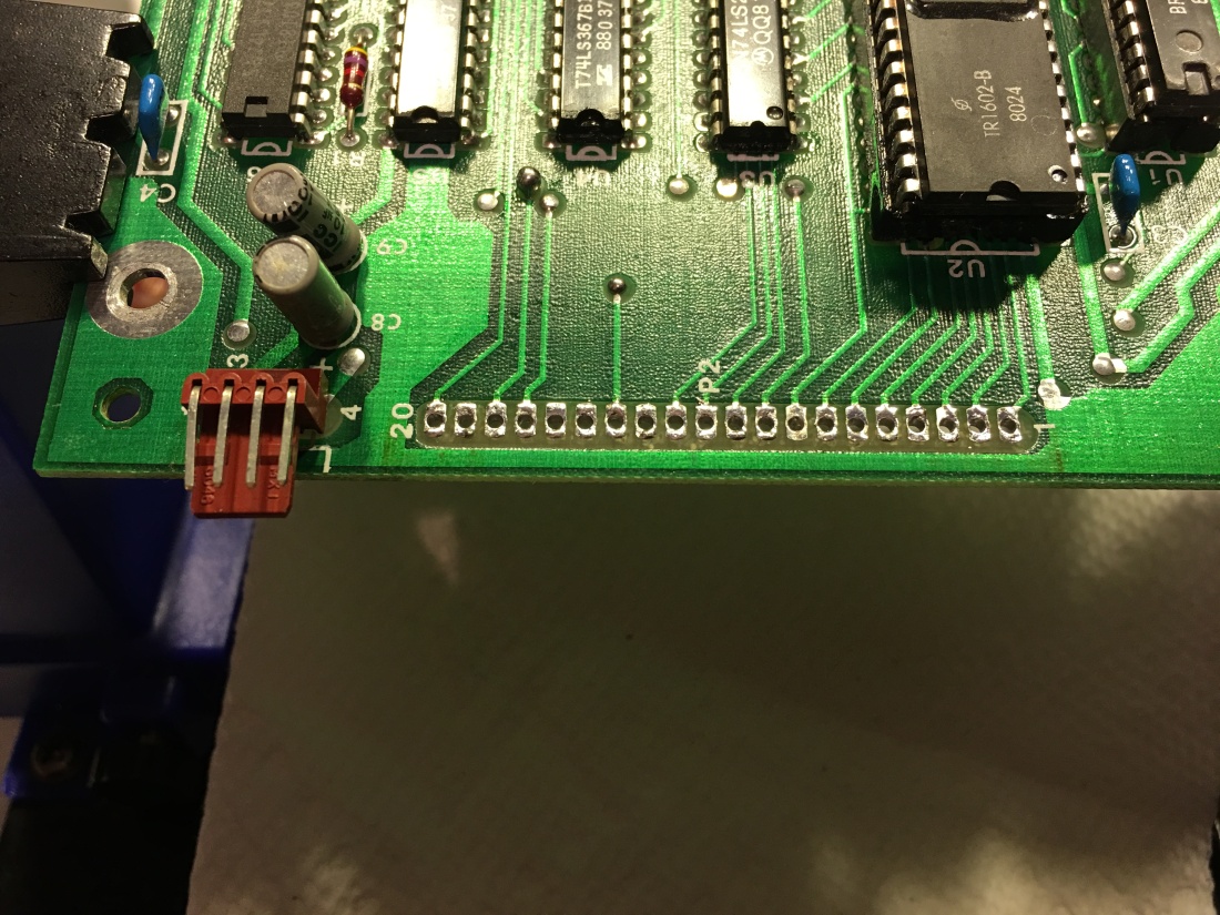
Once all the connections were clean and free of solder, I proceeded to install pin headers in all the locations.

IMG_0322(2)IMG_0323(2)IMG_0324(2)Then all that was left to do was to connect the boards with short 40 pin IDC ribbon cables.  The key to this is to be sure and use the same row of holes on each end thus using 1/2 of the wires in the cable.  Here are some images of the cables connected.

Now that I had all the connections between the boards modernized and reliable, I buttoned up the back end and began to focus on the drives.

In the next post, I will outline my progress by showing the installation of a GOTEK floppy drive emulator along side a double sided 5 1/4″ floppy drive in the drive 0 and 1 position with a toggle switch that will allow switching which drive is 0 and which is 1 allowing to boot from either.


TRS-80 Model III disassembly Part 2

The first step I had even before applying power to the computer was to take it apart and do a visual inspection.

I flipped the machine over and with my handy #2 Philips screwdriver went to work. I noticed that some of the screws wobbled. Once I finished removal, I could see why.

All the plastic mounts with the exception of one, had broken free from the upper case. The one that didn’t break free from the case, broke in two. Well, that explained the loose screws.

Other issues I found after removing the main logic board cover included dislodged flex cables on the main board, badly degraded flat flex cables between the main board and rs232/floppy controller daughter boards, and bent sheet metal.

I reconnected the flex cables on the main board and removed the flex cables from the floppy controller and rs232. After looking everything else over, I decided to apply power to see if she was alive. The results…

It’s alive!!

In the next post, I’ll go over some modifications to replace the flex cables and change the drive configuration a bit.

My TRS-80 Model III story… Part 1

My story started when I came across an ad on eBay offering a 48K disk based TRS-80 Model 3 for $49 + $67 shipping. The machine was advertised as ” ESTATE ITEM I plugged unit in but could not get it to turn on, for parts or repair, AS IS, NO RETURNS please see pictures

In the ads photos there was obvious case damage, but the monitor didn’t have that big black spot in the middle indicative of a broken yoke.

What caught my eye was that the computer was located within a two hour drive of my house. So I decided I’d make an offer. I offered $25 with free local pickup, and to my pleasant surprise, my offer was accepted.

Now, I am the happy owner of a model 3!

The next few articles will spell out my process of diagnosis and repair.

Homebrew TPDD Cable Comparison to OEM

The boards came in from OSH Park, and I’ve compared the OEM cable to the cable built with my PCB.

I found an OEM cable for a brother FB100 portable disk drive on ebay, and split it in half to make two of the cables.  The third one, I used the flat cable from A Cisco serial cable, and modified a 16 pin PCB mount header connecter to use just the inside 8 pins with the key.

I purchased 3 DB25 Male connectors with shrouds for the computer end.

Here’s what the stages looked like soldering the PCB.


After I assembled my cable, I checked the through connections checking for continuity and shorts.  All checked good.  I then checked the 3 paths that have the transistors to compare them to the OEM cable I have.  The results are shown below.


The upper 3 Images are of the OEM cable and the bottom 3 are my cable.  The newer transistors have a slightly higher gain with a little lower forward voltage.  When connected, my cable behaves just like the OEM.

The only issue I had was with my model 100.  The opening for the DB25 is too narrow for the shroud on the connector I purchased to fit into easily.  The Model 102 has more clearance around the DB25 and the cable fits easily.

Here’s a closeup of one of the transistors and the reason I think this might be Marty’s mysterious device.

fullsizeoutput_66f

As you can see, it is clearly marked “14” just as Marty said the devices he found were.

I know this might be re-inventing the wheel, but just thought I’d toss my idea in the mix.


Tandy Portable Disk Drive “TPDD” Cable

In 1989, a gentleman named Marty Goodman posted the his discoveries “TPDD.DO” regarding his disassembly of his Tandy Portable Disk Drive “TPDD” cable.

He noted the following:

”There were three odd little surface mount components in the circuitry for the DTR, TXD, and RTS lines going FROM the TPDD TO the DSR, RD, and CTS pins of the DB25. All other lines were wired straight thru. The three odd devices looked like litte resistors or capacitors, and had the designation “14” on them. Curiously, they had THREE leads, two on one long side and one in the middle of the other long side of each of these tiny rectangular components.”

After probing and measuring he came to the conclusion that these devices behaved like a diode/resistor combo.

Since that time the internet has grown and there is much more  information available. With some quick research and checking an original cable with a device checker, I have come to the conclusion that the devices may actually be PNP Transistors with built in bias resistors (DTA114EKA).

DTA114EKA_Equiv_Package
DTA114EKA_Equiv_Circuit

Note that these transistors are marked with the number 14 and the combined resistance base to emitter is 20K, close to the 22K Marty found and match his description.

I have designed a cable using these devices oriented the same as I found them in the the OEM cable I have. I am designing a PCB that will mount into a DB 25 connector shroud.

Now, I know I used a DB9 for my test cable, but the PCB is designed for the DB25. I will  share the pcb once I have proven the design. Here’s the layout.

To be continued…